# MAX78000 Cats vs Dogs Demo
Description
-----------
The model trained in this demo is used to classify images of cats and dogs. 25000 images dataset is used to train the model. The dataset can be downloaded using�[https://www.kaggle.com/c/dogs-vs-cats/data](https://www.kaggle.com/c/dogs-vs-cats/data)�link. The input size is 128x128 pixels RGB which is 3x128x128 in CHW format.
The code uses a sampledata header (sampledata.h) file to test a pre-defined input sample. The example also supports live capture from camera module and displays the image on the TFT LCD.
## Software
### Project Usage
Universal instructions on building, flashing, and debugging this project can be found in the **[MSDK User Guide](https://analogdevicesinc.github.io/msdk/USERGUIDE/)**.
### Project-Specific Build Notes
* This project comes pre-configured for the MAX78000EVKIT. See [Board Support Packages](https://analogdevicesinc.github.io/msdk/USERGUIDE/#board-support-packages) in the UG for instructions on changing the target board.
* This project supports output to a TFT display. When building for the MAX78000EVKIT, the display is **enabled** by default.
* To _disable_ the TFT display code, comment out `PROJ_CFLAGS += -DTFT_ENABLE` in [project.mk](project.mk)
```Makefile
ifeq "$(BOARD)" "EvKit_V1"
# PROJ_CFLAGS+=-DTFT_ENABLE
IPATH += TFT/evkit/
VPATH += TFT/evkit/
endif
```
* When building for the MAX78000FTHR, the TFT display is **disabled** by default. The compatible 2.4'' TFT FeatherWing is an optional display that does not come with the MAX7800FTHR. It can be ordered [here](https://learn.adafruit.com/adafruit-2-4-tft-touch-screen-featherwing)
* To _enable_ the TFT display code, uncomment `PROJ_CFLAGS += -DTFT_ENABLE` in [project.mk](project.mk)
```Makefile
ifeq "$(BOARD)" "FTHR_RevA"
# Only Enable if 2.4" TFT is connected to Feather
PROJ_CFLAGS+=-DTFT_ENABLE
IPATH += TFT/fthr
VPATH += TFT/fthr
endif
```
* By default, this project builds for ["offline" mode](#offline-mode), which uses a static "known answer" input. To enable real-time captures in ["camera" mode](#camera-mode), comment out `#define USE_SAMPLEDATA` defined in [main.c](main.c).
## Hardware
### MAX78000EVKIT operations
* If using camera and TFT LCD, connect OVM7692 camera board directly (without 90 degree adapter) to 'J4 Camera' header facing out and place TFT display on the display header.
* Connect a USB cable between the PC and the CN1 (USB/PWR) connector.
* Place jumper P0\_0 and P0\_1 on UART\_0\_EN header JH1.
* Open a serial port application on the PC and connect to Ev-Kit's console UART at 115200, 8-N-1 configuration.
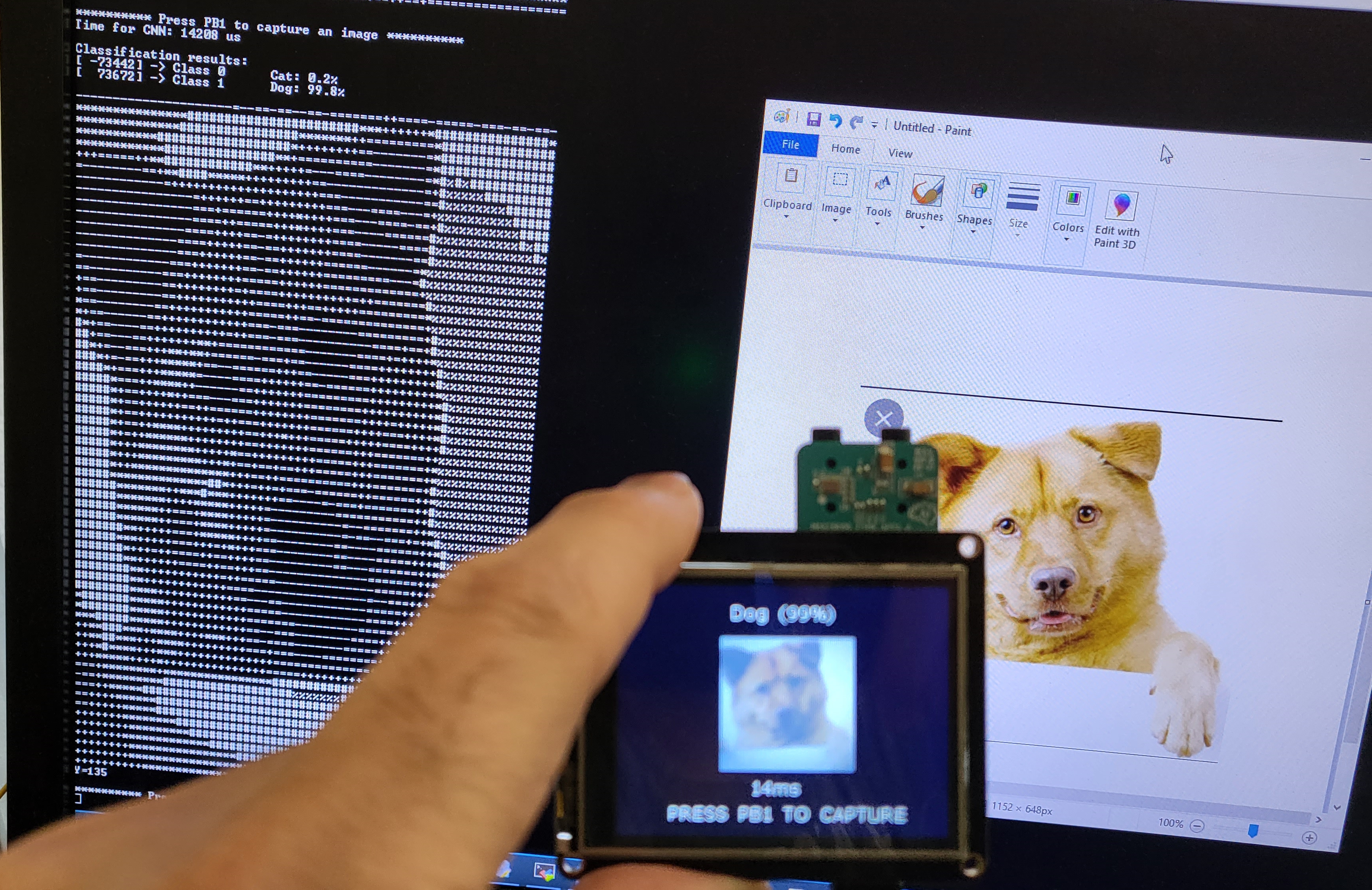
This demo is operated in two modes: Real-time data using Camera module or using sample image header file in offline mode.
In either mode, pushbutton trigger PB1(SW2) is used to capture and load an image into CNN engine. User is prompted to press PB1 to load an image
### MAX78000FTHR operations
User should use PC terminal program to observe **cats-dogs_demo** result as described in "Terminal output" section with help of the ascii art representation of the captured image.
This TFT display comes fully assembled with dual sockets for MAX78000 Feather to plug into.
While using TFT display keep its power switch in "ON" position. The TFT "Reset" button also can be used as Feather reset.
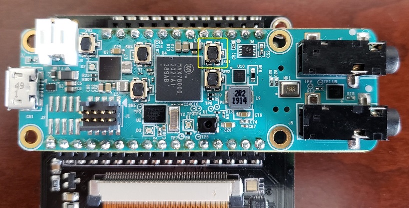
Press PB1 (SW1) button to start demo.
 The PB1 (SW1) button is located as shown in picture bellow:
 ### Camera Mode
This mode uses OVM7692 camera module to capture an image in RGB888 format. Since the model is trained using 128x128 pixel image, the PCIF peripheral captures 128x128 pixel image and displays it on LCD.
### Offline Mode
To operate in this mode, uncomment "#define USE\_SAMPLEDATA", defined in main.c.�
This mode uses a header file "sampledata.h" containing RGB image data and it should be included in the project to use it as an input to the CNN network.�
To create your own header file follow these steps:
1. Navigate to Utility directory. $ cd Utility
2. Download cat or dog image in this directory.
3. Open 'rgb.py' file and change the name of the image file on line 8. im = (Image.open('image_filename.format')). Save the changes.
4. Now generate a header file using this command: python3 rgb.py
5. Use this header file in your main.c
Terminal output
---------------
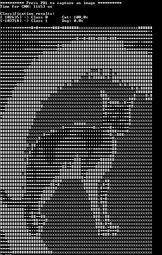
The Console UART of the device will output the classification result + an ascii art demonstration of the picture :
### Camera Mode
This mode uses OVM7692 camera module to capture an image in RGB888 format. Since the model is trained using 128x128 pixel image, the PCIF peripheral captures 128x128 pixel image and displays it on LCD.
### Offline Mode
To operate in this mode, uncomment "#define USE\_SAMPLEDATA", defined in main.c.�
This mode uses a header file "sampledata.h" containing RGB image data and it should be included in the project to use it as an input to the CNN network.�
To create your own header file follow these steps:
1. Navigate to Utility directory. $ cd Utility
2. Download cat or dog image in this directory.
3. Open 'rgb.py' file and change the name of the image file on line 8. im = (Image.open('image_filename.format')). Save the changes.
4. Now generate a header file using this command: python3 rgb.py
5. Use this header file in your main.c
Terminal output
---------------
The Console UART of the device will output the classification result + an ascii art demonstration of the picture :
 ### References
https://github.com/MaximIntegratedAI/MaximAI_Documentation
### References
https://github.com/MaximIntegratedAI/MaximAI_Documentation